
Reconstruct provides the ability to create an orthographic image of any surface of your reconstruction, i.e. point cloud. The surface can be curved, e.g. a chimney or cooling tower, it can be uneven, e.g. surface of a construction site, or it can be even, e.g. the surface of one side of a bridge span. The tool utilized in Reconstruct is called the Surface Mapping Tool (SMT).
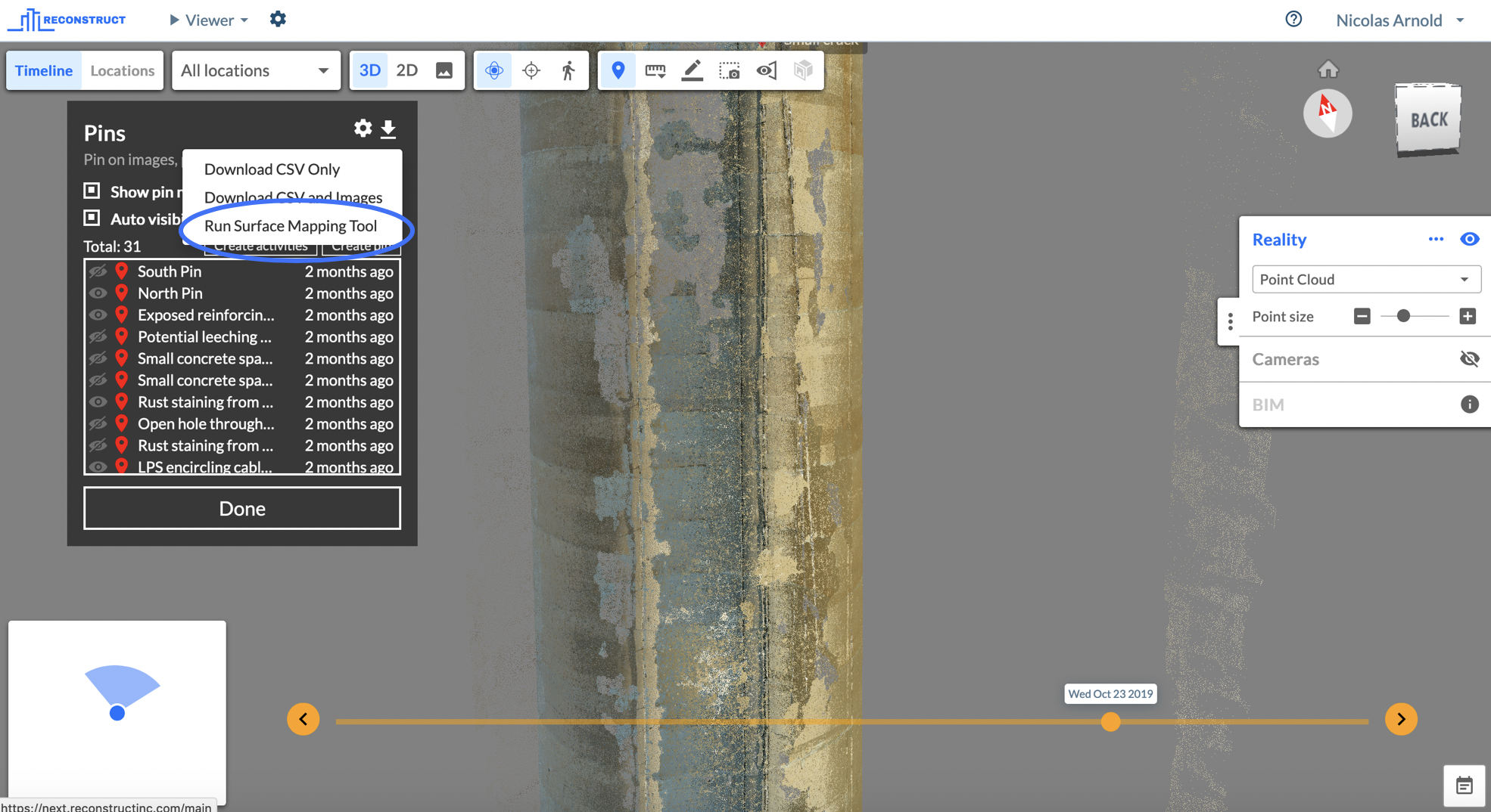
You find this tool in the Pin tool as the third item in the download menu. Make sure that your point cloud is visible - go to the Reality section of the Control Panel on the right side of the screen and click on the eye symbol to turn on the point cloud, if it is not visible already.
You can create an orthographic image from a point cloud very easily with the following steps:
- Click on Create +
- Select the Surface Type of the shape that you want to create an orthographic image from, e.g. Plane, Cylinder, Cone. This example creates a Cylinder.
- Provide a Name for the new image
- Place at least four Anchor Points on the surface, ideally random and not at the same height or in one line. Click on the plus sign (+) to add a new point and then click on the surface to place that point. Repeat this process for as many points as you want to place, at least four.
For Cylinders, you must place four points on the same height level of your surface and two more points elsewhere. Ideally, the four points on the same height should be placed in equal distance around the cylinder of your point cloud.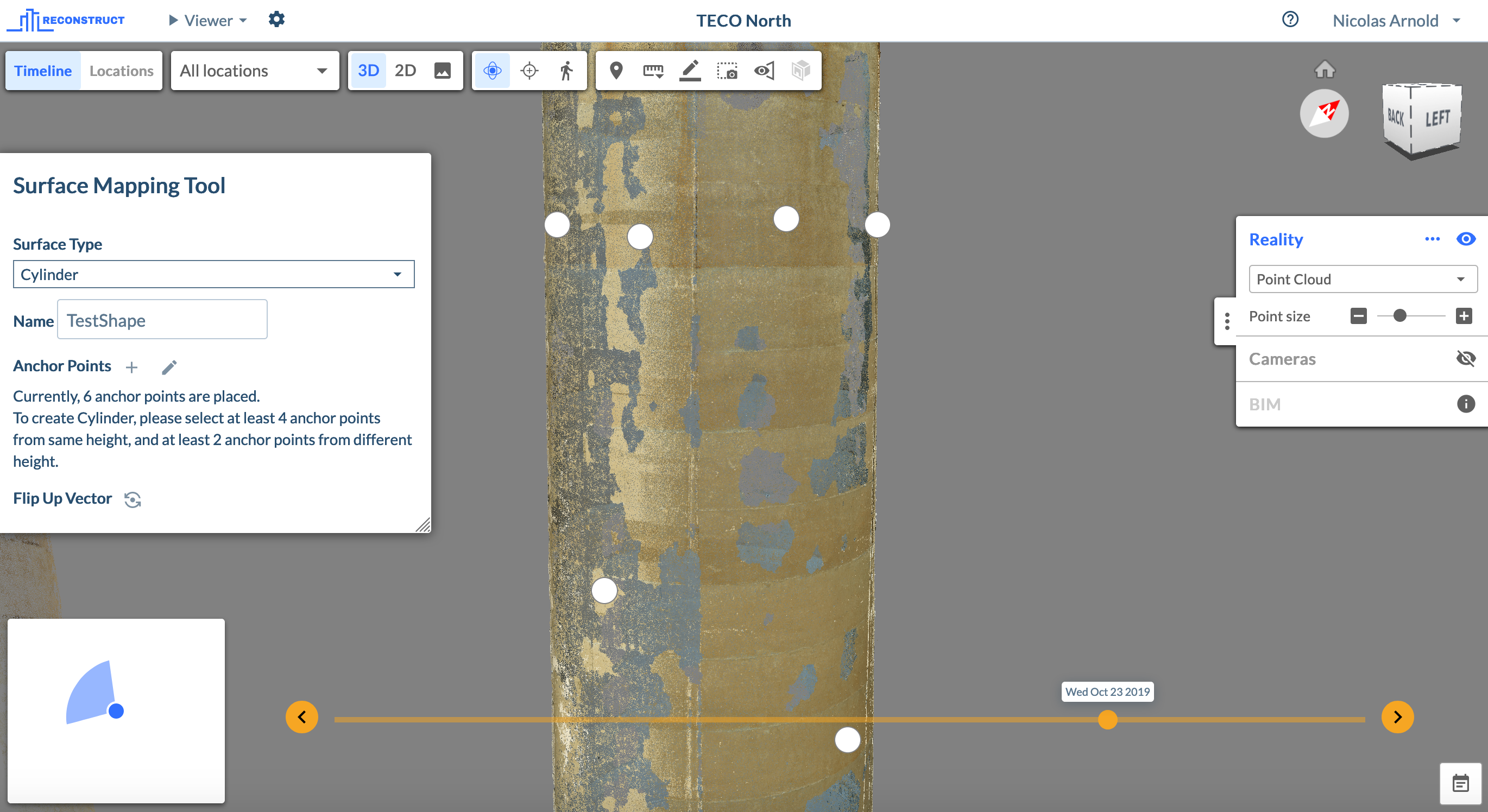
For Planes, you have to provide the four points in a way so they are not in one straight line.
Make sure that the placed points (white dots) are placed on the surface that you want to work with and not behind that surface by mistake. To check, orbit the reality model slightly to check the placement.
To change the location of a point, you can left click on the point and while holding down the left mouse button, move the point to the desired location.To remove a point that was placed at the wrong location, right click on the point and choose to delete it.
- Once you have created sufficient points on your reality model, the Fit button on the bottom of the Surface Mapping Tool dialog box becomes active. Click it and the surface will be created - in the this example a cylinder:

- In the example of the cylinder, the green line without the arrowhead marks the starting line of the orthographic image. You can choose the exact location of that line by manipulating the Starting Angle. Simply adjust the slider and you will see the green line move around the cylinder.
- The Tolerance allows you to set the range of points to include in your orthographic image. In the example of the cylinder, adjusting the slider makes the cylinder shape thicker if you go towards the plus (+) sign. This is useful for hyperboloid structures like cooling towers where you can fit in all the points into a cylinder shape with a large tolerance - in other words a thick cylinder shape that includes all points of the hyperboloid shape.
- Once you are happy with the fit, you can click Create. This will add another line into the table of the Surface Mapping Tool dialog.
- To start the processing, click the play button () to set the resolution and the page layout. For instance, a tall structure like a chimney you would want to create with one column but in two rows.
The creation of the orthographic image will take a few minutes. Once you have received an email when processing has finished, you can download the image through the cloud symbol in the Surface Mapping Tool.
Comments
0 comments
Article is closed for comments.