
The 3D Measurement Tool allows users to interactively conduct a variety of measurements. This article offers guidance on how to utilize and apply the methods of the 3D measurement tool:
- Coordinate: Display GPS position of selected point.
- Angle: Measures angles in degrees.
- Distance: Measure distance between points.
- Height: Measure height between points.
- Footprint Area: Measures the surface area of a plane by projecting the selected points onto the x-y (ground) plane.
- Plane-fit Area: Measures the surface area to a plane fitted to the selected points.
- Surface Area: Measures the surface area between selected points.
- Cut & Fill Volume: Performs volumetric measurement of point cloud of selected region.
3D Measurement Tool
Opening Measurements
The 3D Measurement Tool is accessible from the main toolbar.
General Measurement Selection and Adjustments
The measurement tools operate in a consistent manner.
- Select Method: Start by choosing the desired measurement method.
- Begin Measurement: Left-click to set the initial point.
- Continue Measurement: Keep left-clicking to add more points.
- Finish Measurement: Press "Enter" or "ESC" on the keyboard to complete the measurement.
- Adjust Point Placement: Click and hold the left mouse button on a point, drag it to a new location, and release the button to finalize the adjustment
Magnifying Lens in Image View
The Magnifier Lens precisely indicates the pixel you are selecting, offering a comprehensive view of the scene. This ensures you can make the perfect selection with confidence.
- The Reconstruct interface is minimized to allow focus solely on the task at hand.
- Arrow keys can be used for navigation during measurements, with all panoramas hidden.
Angle, Distance, Height, Footprint Area, Plane-fit Area, and Surface Area measurements are all now enhanced with the Magnifier Lens feature.
Clear Measurements
Use this to clear any measurements that you may have displayed on your screen.
Units
Displayed units may be changed by accessing Viewer Settings from the top menu.
Select the measurement unit for the viewer: foot, inch, meter, centimeter, millimeter.
Measurement Methods
 Calibrate
Calibrate is used to set the scale of the project or a specific 3D reality model. The model must be calibrated before taking any measurements.
- Calibrate BIM: If the project has an active BIM and calibration is required, select two points and enter the displayed value and save. This will set the scale exactly to BIM. This action is typically performed once during project setup.
- Calibrate Reality to Field Measurement: If there is no BIM and calibration is required for a reality model, select two points where the distance between them is known and set the value.
- Calibrate Reality with Alignment to Design: If the exact scale of a reality model is unknown, use 2D or 3D model alignment to best scale the model.
How to Calibrate:
- Select Calibrate from the measurement interface.
- Navigate in the view and left click to select the first point.
- Navigate in the view and left click to select the second point.
- Enter the field measurement, known distance, or displayed value (if unknown) in input field.
- Click Save.
 Coordinate
Coordinate measurement displays the GPS or XYZ coordinates from a point cloud.
- Select Coordinate measurement with Reality visible from the Control panel.
- Select the point on the point cloud to view coordinates.
- Read the Latitude, Longitude, Altitude.
Note: The reality model must have GPS coordinates to display coordinate.
 Angle
Angle
Angle measurement displays the angles between three points.
- Select Angle measurement.
- Select three points by left clicking to draw a triangle.
- After the third point is placed, the angles are displayed.
- Adjust the points to refine the measurement.
 Distance
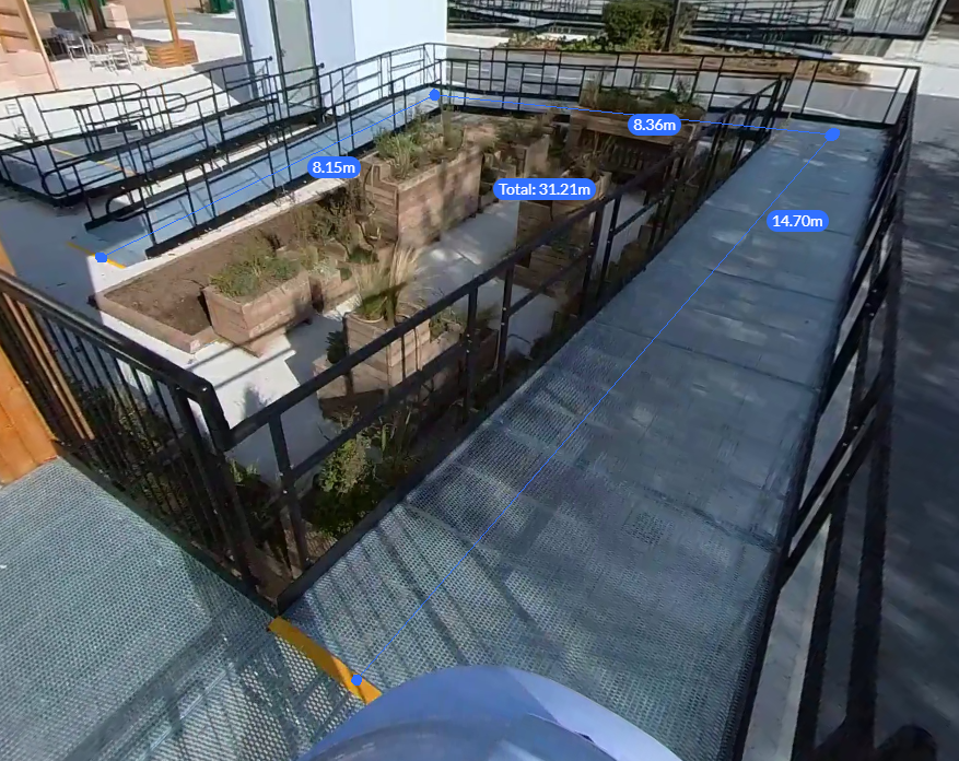
Distance measurement measures point to point distance or multi-line distance with total distance in 3D.
- Select Distance measurement.
- Select the first point with a left click.
- Select the subsequent point with a left click.
- Continue selecting points or conclude by pressing "Enter" or "Esc".
 Height
The Height measurement computes the vertical distance between two points.
- Select Height measurement.
- Select the top or the bottom point to start.
- Select the second point (e.g. on the floor or on the ceiling). This point does not need to be directly above or below the first point and can be on a surface parallel to the x-y plane.
 Footprint Area
The Footprint area computes the area of a polygon projected on the x-y plane.
- Select Footprint Area measurement.
- Select the first point with a left click.
- Select at least two more points for the shape to display the calculated area.
- Finish by hitting "Enter" or "ESC" on your keyboard.
 Plane-fit Area
Plane-fit area measurement calculates the area of a polygon bounded by selected points fit on a plane.
- Select Plane-fit area measurement.
- Select the first point with your cursor that shows the red dot
- Select at least two more points for the shape to display the calculated area.
- Finish by hitting "Enter" or "ESC" on your keyboard.
 Surface area
The Surface Area measurement calculates the non-planar surface area by summing of the area of the triangles which form the surface..
| 1. |
Select Surface area measurement. |
||
| 2. |
Left click to select the first point on the boundary. Continue to place points along the edge to form a smooth polyline. Hit "Enter" to complete boundary points. |
||
| 3. |
Select inner points to add detail to the surface. |
||
| 4. |
Left click to select the first inner point on the surface. Continue to place points at high and low points on the surface or simply place enough points to add shape to the surface. Hit "Enter" to complete inner points and the surface area measurement. |
||
| 5. |
Navigate in 3D to inspect the surface. Adjust points as needed. If the boundary or surface is not well defined, start the surface area measurement again. |
 Cut & Fill Volume
The Cut & Fill Volume computation is a crucial process in earthworks projects, allowing for the calculation of the amount of earth that needs to be removed (cut) and added (fill) to reach a desired level of terrain for construction and landscaping projects.
| 1. |
Select Cut & Fill Volume measurement and then select "Create New." |
||
| 2. |
Left click to place points around the edge of the cut or fill to be measured. As shown, cut and fill is used to quickly estimate the amount of materials in stockpiles. Hit "Enter" to complete boundary points. |
||
| 3. |
Select the Base Surface option (best fit, lowest fit or plane fit) to choose the basis of the ground plane for volume calculation. Click refine to compute.
|
||
Each option serves a specific purpose, depending on the terrain's complexity and the required accuracy level for the volume calculations. |
|||
| 4. |
Click to save. Enter name of current measurement. |
||
| 5. |
Cut & Fill Volume measurements will be saved to the project for any user to view. Click "Done" to close window.
Click "Detail" to view or edit measurement. |
||
| 6. |
Edit Measurement: To edit boundary, navigate to the point cloud that was measured and edit by clicking pencil icon. Edit base surface by changing the method and clicking "Refine" Delete Measurement: Click trash icon to delete measurement. Measure Volume Changes Over Time: To measure changes over time, maintain the same boundary while analyzing various reality captures. Select dates for which you have images or data of the same spot, ensuring they are properly aligned with each other. This method allows you to track and understand alterations within a specific area accurately. |
||
Comments
0 comments
Please sign in to leave a comment.