
This is the newly introduced yet most simple orthographic view in Reconstruct. You may use this view in cases that you want to compare a drawing with either Reality (newly introduced reality for 2D environment) or 360 images (under Camera). In this view, you have access to Reality, Cameras, and drawings in your control panel. In this view, the user is only allowed to move in directions parallel to the plane (left click and hold) and zoom in and out.
Control Panel
In this view, there are the three different elements that are available to work with are Reality (Newly introduced for 2D), Camera (which includes three different sources: 360 images, images from video captures, and geolocated images), and drawings.
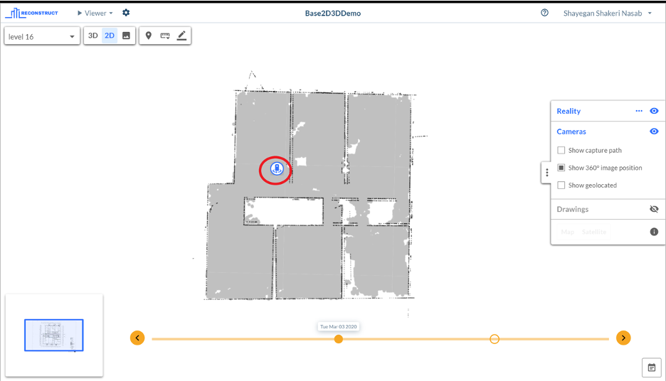
Reality: In the image below, you can see the new Reality visualization for 2D view which is able to extract the wall boundaries of each capture. In this screenshot, the drawing is turned off to better show the ability of this visualization to show wals locations and positions (in back dots).
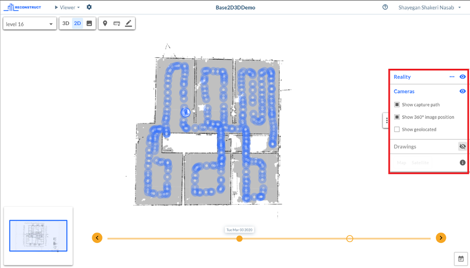
Camera: If “Show capture path” is turned on, blue so-called “donuts” will represent camera locations where you can jump into the image by clicking them. These Images are ones which used to process the visible point cloud (Reality)
Second source of Images are the ones which were taken one-time by using capture app. These Images and camera points are represented with the icon shown in the image below.
Third source of Images that can be shown in the Camera is geolocated images that are available only if the GPS data was stored along with the image.
Drawings: from this section in the Control panel, you can select your desired drawing from the drop-down list, change the visibility of the drawing (and turning it on/off) and align the reality (point cloud) with the drawing by hitting the “three dots” button.
Drawings:Here you are able to select your drawing from the drop-down list of different drawings attached to this specific location. You can also change the visibility of the drawing. Hitting the “three dots” button will toggle the alignment tool in 2D.
Toolbar
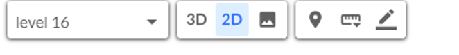
In this View the toolbar is limited to the location tool where you can select the desired location. Switching to other views and pins, measurement tools and markup tool.
Navmap
In this view, you still can benefit from the Navmap from the bottom left of the screen. If you hover the mouse to the small Navmap window, the window will get maximized. The major difference of Navmap in 2D View compared to 3D is that location of the user is substituted by showing a window in blue rectangle which indicates the original limits of the viewer in the main window.

If you already have a point cloud for this location, you can switch between Drawing/Reality. In the toolbar below the Navmap you have a few options. First Button minimizes the Navmap. The rest of the buttons are usually disabled in 2D view except the “three dots” which enable you to align the drawing.
Image View
Image view only enabled when at least one 3D point-cloud exists in that specific location. If that is the case, by clicking on Image view, the viewer will jump into the nearest camera position and load the image taken from that spot. In this view, your control panel includes Reality, Images, and BIM.
Control Panel
In this View’s Control Panel, you can move between different images, and prioritize BIM visibility over images by selecting “Show BIM overlay”.
Reality: This section will enable the user to load point clouds assigned to a specific location and date (in timeline). Just like 3D view, point cloud sizes can also decrease/increase.
Image: in the Image section, you can navigate to other images by either clicking on the arrows in the control panels or using arrow keys in the keyboard. You can also zoom in/out using mouse scroll.
BIM: BIm enables you to choose what visualization you want to use, and prioritize BIM visibility over images by selecting “Show BIm overlay”.
Comments
0 comments
Article is closed for comments.